Lab-1 Experiment: Exploring Visual Effects with 6502 Assembly
Introduction
In this section of Lab 1, we will experiment with the original bitmap code to observe how small changes in the assembly instructions can create different visual effects on the bitmapped display. We will learn more about how the 6502 processor manages data manipulation and how these operations translate into visual output by changing the code and examining the outcomes. We can investigate the connection between memory addressing, assembly instructions, and the final graphical display with the aid of these experiments.
Experiment 1: Adding "tya" Instruction
Objective:
Add the "tya" instruction after the loop: label and before the "sta ($40),y" instruction. Observe the visual effect and explain why it occurs.

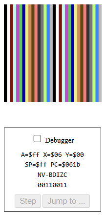
The screen displays a gradient of colors instead of a solid yellow. The gradient repeats every 16 pixels horizontally.
Explanation:
The TYA instruction transfers the value of the Y register (which ranges from 0 to 255) into the accumulator. This value is then used as the color code for each pixel. Since the Y register increments by 1 for each pixel, the color changes gradually, creating a gradient. The gradient repeats every 16 pixels because the color codes are based on the lower 4 bits of the Y register (0x00 to 0x0F).
Experiment 2: Adding "lsr" Instruction
Objective:
Add the "lsr" (Logical Shift Right) instruction after the "tya" instruction. Observe the visual effect and explain why it occurs.

Experiment 2: Adding "lsr" Instruction
Objective:
Add the "lsr" (Logical Shift Right) instruction after the "tya" instruction. Observe the visual effect and explain why it occurs.
Observation:
The gradient becomes less intense, with fewer colors displayed. The colors appear darker and more compressed.
The gradient becomes less intense, with fewer colors displayed. The colors appear darker and more compressed.
Explanation:
The LSR instruction shifts the bits in the accumulator to the right, effectively dividing the value by 2. This reduces the range of possible color values, resulting in fewer colors and a darker gradient.

Objective:
Repeat the above experiment with two, three, four, and five LSR instructions in a row. Observe and explain the effect in each case.
Two LSR:
Explanation:
Two LSR:
Explanation:
Each LSR instruction halves the value in the accumulator. After two LSR instructions, the value is divided by 4, reducing the range of color values further. This results in fewer colors and a darker gradient.

Three LSR:
Explanation:
After three LSR instructions, the value is divided by 8, further reducing the range of color values. This results in a mostly dark screen with only a few visible colors.

Four LSR:
Explanation:
After four LSR instructions, the value is divided by 16, leaving only a small range of color values.

Five LSR:
Explanation:
After five LSR instructions, the value is divided by 32, Which is now making the lines to come horizontally with only 8 colors repeating.

Experiment 4: Using "asl" Instead of "lsr"
Objective:
Repeat the tests using ASL (Arithmetic Shift Left) instructions instead of LSR. Observe and explain the effect.
One ASL:
Explanation:
One ASL:
Explanation:
The ASL instruction shifts the bits in the accumulator to the left, effectively multiplying the value by 2. This increases the color values, resulting in brighter colors.

Two ASL:
Explanation:
After two ASL instructions, the value is multiplied by 4, increasing the color values further. Resulting in 4 color set 8 times making it 32 columns.

Three ASL:
Explanation:
After three ASL instructions, the value is multiplied by 8, we get 2 color set 16 times making it 32 columns.
 Four ASL:
Explanation:
Explanation:
After four ASL instructions, the value is multiplied by 16, the least significant nibble (low 4 bits) of Y will move to the high nibble, and the higher bits will be lost when they exceed 8 bits (the register size).
This results in A being either 0 or a multiple of 16, which means the color value written into video memory is likely 0 most of the time (black).
This results in A being either 0 or a multiple of 16, which means the color value written into video memory is likely 0 most of the time (black).

Explanation:
With 5 ASLs, color values are mostly 0 or multiples of 32 → almost entirely black screen.

Objective:
Test the effect of adding one to five consecutive INY (Increment Y) instructions in the original code. Observe and explain the effect.
Two INY:
Observation:
The screen has alternating horizontal lines of yellow and black.
Explanation:
Each INY instruction increments the Y register by 1. With two INY instructions, the Y register increments by 2 for each loop iteration, causing the loop to skip every second pixel. This creates a pattern of alternating yellow and black lines.

Three INY:
Observation:
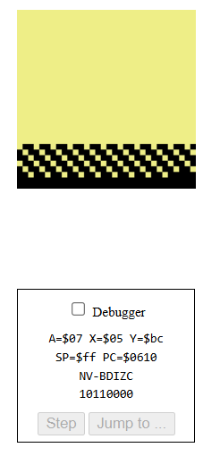
From top-left to bottom-right, the screen fills diagonally, forming a checkerboard pattern in black and yellow. Eventually, the entire screen turns yellow as all of the black spaces are filled.
Explanation:
Three iny instructions are used to create a checkerboard effect by skipping two addresses for each filled pixel. As the loop repeats, the black pixels that were skipped eventually get filled as well.
First image show how it started and 2nd show how it went.

Four INY:
Observation:
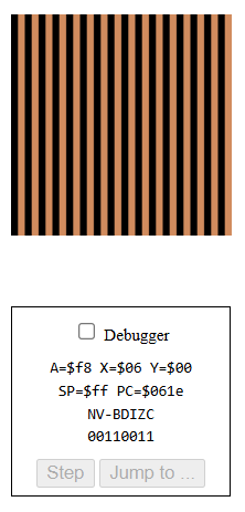
The screen is filled with vertical yellow stripes from top to bottom, much like in 2 iny, but the black spaces are much wider and the yellow stripes are much thinner.
Explanation:
Four iny instructions create a pattern with thick black spaces and thin yellow stripes by skipping three addresses for each filled pixel.

Five INY:
Observation:
A checkerboard-like pattern fills the screen diagonally from top-left to bottom-right. But, in contrast to 3 iny, the pattern has bigger blocks. After four iterations, the entire screen turns yellow.
Explanation:
For every pixel filled with 5 iny instructions, larger gaps are skipped. Eventually, the screen turns completely yellow as the skipped spaces are filled in with bigger blocks. First pic show how it start and second shows how it ended.


Conclusion
These experiments demonstrated how small changes in assembly code can significantly alter the visual output on the bitmapped display. By manipulating the Y register, accumulator, and using shift operations, I observed gradients, patterns, and color variations. This hands-on experience with the 6502 emulator deepened my understanding of assembly programming and its applications in graphical displays. I look forward to tackling more challenges and experiments in future labs
Each INY instruction increments the Y register by 1. With two INY instructions, the Y register increments by 2 for each loop iteration, causing the loop to skip every second pixel. This creates a pattern of alternating yellow and black lines.
Three INY:
Observation:
From top-left to bottom-right, the screen fills diagonally, forming a checkerboard pattern in black and yellow. Eventually, the entire screen turns yellow as all of the black spaces are filled.
Explanation:
Three iny instructions are used to create a checkerboard effect by skipping two addresses for each filled pixel. As the loop repeats, the black pixels that were skipped eventually get filled as well.
First image show how it started and 2nd show how it went.
Four INY:
Observation:
The screen is filled with vertical yellow stripes from top to bottom, much like in 2 iny, but the black spaces are much wider and the yellow stripes are much thinner.
Explanation:
Four iny instructions create a pattern with thick black spaces and thin yellow stripes by skipping three addresses for each filled pixel.
Five INY:
Observation:
A checkerboard-like pattern fills the screen diagonally from top-left to bottom-right. But, in contrast to 3 iny, the pattern has bigger blocks. After four iterations, the entire screen turns yellow.
Explanation:
For every pixel filled with 5 iny instructions, larger gaps are skipped. Eventually, the screen turns completely yellow as the skipped spaces are filled in with bigger blocks. First pic show how it start and second shows how it ended.
Conclusion
These experiments demonstrated how small changes in assembly code can significantly alter the visual output on the bitmapped display. By manipulating the Y register, accumulator, and using shift operations, I observed gradients, patterns, and color variations. This hands-on experience with the 6502 emulator deepened my understanding of assembly programming and its applications in graphical displays. I look forward to tackling more challenges and experiments in future labs

Comments
Post a Comment